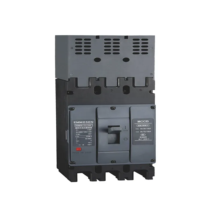
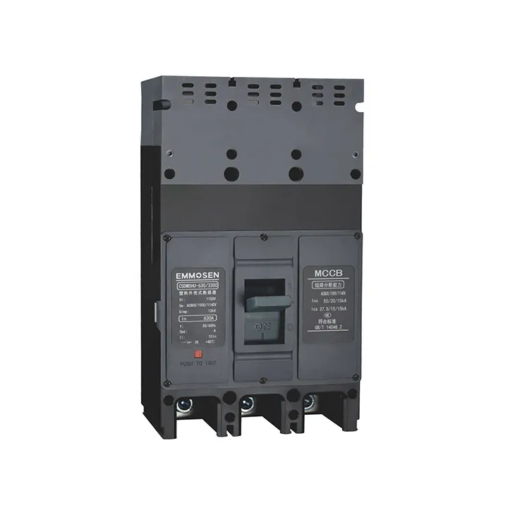
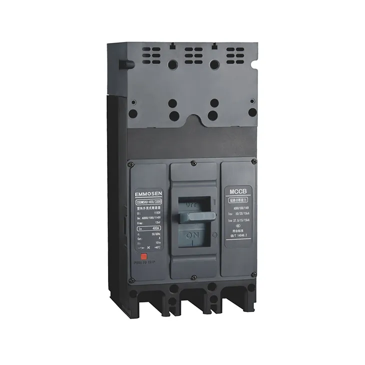
CSDM5HU series high voltage circuit breaker (referred to circuit breaker) is specially designed for high voltage electrical system with rated voltage up to 1140V and rated current 63A~800A. This circuit breakers can effectively protect electrical systems like the output loading of the string Inverters and others such as the loading capacity of the AC combiner box in the photovoltaic systems.
Meet the standard:
GB/T14048.1 Low-voltage switchgear and control equipment - Part 1: General Rules
GB/T14048.2 Low-voltage switchgear and control equipment - Part 2: Circuit breakers
• The elevation of the installation site can't exceed 2000m;
• The temperature is not higher than +70°C, not lower than -45°C(Over +40°C , use it through capacity reduction, the specific need to negotiate with the manufacturer);
• Atmospheric conditions: such as 90% at 20°C, and taking into account the condensation on the surface due to temperature changes, When the arounding temperature is 40°C, the relative humidity of the atmosphere does not exceed 50%, and a higher relative humidity is allowed at a lower temperature.
• The pollution level is 3;
• Installation category is III;
• Installation magnetic field: The magnetic field of the installation position does not exceed 5 times the earth magnetic field in any direction;
• In a medium without explosion risk, and there is no gas and conductive dust sufficient to corrode metal and destroy insulation in the medium;
• Where there is no snow erosion;
• Installation conditions: It can be installed horizontally or vertically. There should be no significant impact or vibration at the installation place.
• It should not be installed in inflammable and explosive places.
• The circuit breaker has the isolation function, the symbol is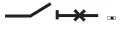
|
Rated current (A) |
63 |
80 |
100 |
125 |
160 |
180,200,225 |
250 |
280,300 |
315,350 |
400 |
|
Cross-sectional area(mm2 ) |
16 |
25 |
35 |
50 |
70 |
95 |
120 |
185 |
185 |
240 |
|
Rated current (A) |
Copper Bar |
Copper Bar |
||
|
Root number |
Cross sectional-area of each wire (mm2 ) |
Root number |
Cross sectional-area of each wire (mm2 ) |
|
|
500 |
2 |
150 |
2 |
30x5 |
|
630 |
2 |
185 |
2 |
30x8 |
|
700 |
2 |
240 |
2 |
50x5 |
|
800 |
2 |
240 |
2 |
50x5 |
Note: 1. Line: 1, 3, 5; Load: 2, 4, 6;
2. The installation method of arcing cover
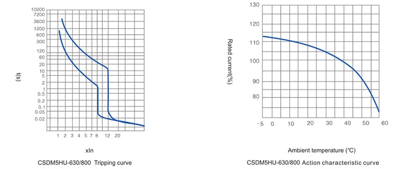
The thermal release of circuit breakers have the particularity of inverse time limit; The electromagnetic release is an instantaneous action, and its characteristics are shown
in the table below.
•Power distribution
|
Circuit breaker rated current (A) |
Thermal release(temperature +40°C) |
Electromagnetic release action current (A) |
|
|
Non-operation time at 1.05 times rated current (cold state) in hours |
Operation time at 1.3 times rated current (hot state) in hours |
||
|
63 |
≥1 |
≤1 |
10In±20% |
|
63 |
≥2 |
≤2 |
|
•Power loss table
|
Model |
Current(A) |
Total Power Loss for Three-phase/Four-phase(W) |
|||
|
Front panel wiring |
Backboard wiring |
Plug in front wiring |
Plug in backboard wiring |
||
|
CSDM5HU-250 |
250A |
62 |
63.5 |
66 |
70 |
|
CSDM5HU-315 |
315A |
67 |
73 |
75 |
78 |
|
CSDM5HU-400 |
400A |
115 |
117 |
120 |
125 |
|
CSDM5HU-630 |
630A |
187 |
192 |
190 |
210 |
|
CSDM5HU-800 |
800A |
260 |
262 |
265 |
290 |
•The capacity reduction coefficient of the rated operating current of the thermal release as a function of the ambient temperature
|
Circuit breaker model |
Ambient Temperature |
||||||
|
+40°C |
+45°C |
+50°C |
+55°C |
+60°C |
+65°C |
+70°C |
|
|
CSDM5HU-250 |
1.0In |
0.983ln |
0.965ln |
0.94ln |
0.924ln |
0.904ln |
0.882ln |
|
CSDM5HU-315 |
1.0In |
0.982ln |
0.962ln |
0.942ln |
0.922ln |
0.901ln |
0.880ln |
|
CSDM5HU-400 |
1.0In |
0.980ln |
0.960ln |
0.940ln |
0.918ln |
0.898ln |
0.877ln |
|
CSDM5HU-630 |
1.0In |
0.979ln |
0.958ln |
0.937ln |
0.912ln |
0.895ln |
0.872ln |
|
CSDM5HU-800 |
1.0In |
0.977ln |
0.956ln |
0.931ln |
0.905ln |
0.893ln |
0.868ln |
Note: When the ambient temperature is lower than 50°C, the product can be used normally, and there is no capacity reduction.
•Elevation reduction
If the altitude exceeds 2000m in the applicable working environment, the electrical performance of the circuit breaker can be referred to the following table.
|
Altitude(M) |
2000 |
2500 |
3000 |
3500 |
4000 |
4500 |
5000 |
|
Maximum Operating Current Coefficient |
1 |
1 |
0.98 |
0.97 |
0.95 |
0.94 |
0.93 |
|
Maximum Operating Voltage(V) |
1140 |
1140 |
1060 |
1000 |
980 |
940 |
900 |
|
1000 |
1000 |
900 |
850 |
810 |
770 |
730 |
|
|
800 |
800 |
720 |
670 |
630 |
600 |
560 |
|
|
Power Frequency Withstand Voltage |
3000 |
3000 |
2650 |
2500 |
2300 |
2150 |
2000 |
|
Rated insulation voltage |
1150 |
1150 |
1040 |
980 |
935 |
890 |
845 |
|
1250 |
1250 |
1140 |
1080 |
1035 |
990 |
945 |
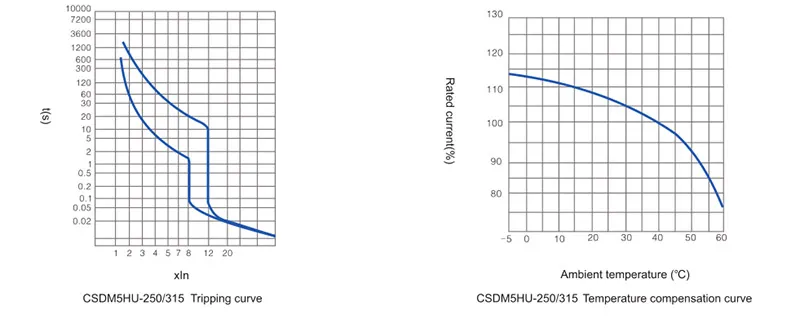
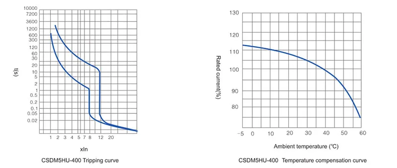
Description: The characteristic curve is measured under cold, three-phase load.
PREV
Clean Our Workshop
NEXT
NULL

GET A QUOTE
+86 18966293209